To install the hardwire kit you will need to locate your vehicles fuse box. The location of the vehicle’s fuse box varies from vehicle make and model. Locations may include underneath the driver’s side dashboard, behind the glove box and underneath the central console. Where in doubt, always refer to your vehicle owner’s manual to determine the location of the fuse box in your vehicle.
Once you have located your fuse box you will need to connect the hardwire kit to both a constant and ACC power source to give your Nanocamplus Dash Camera full functionality.
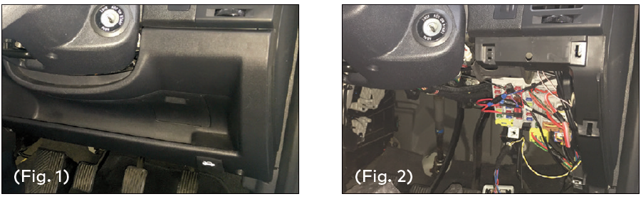
*NOTE: The images in this installation were taken for a vehicle where the fuse box is located under the driver’s side dashboard (Fig. 1 & 2) and should be used as a guide only for a DIY installation. To ensure proper installation Nanocamplus recommends dash camera be installed by a professional technician.
*NOTE: Determine the location of your vehicle’s fuse box before commencing the installation of the hardwire kit. Where in doubt, refer to the vehicle owner’s manual.
ROUTING THE OUTPUT CABLE FROM THE DASHCAM TO THE FUSE BOX
*NOTE: You may need to consult your vehicle manufacturer for instructions on how to remove vehicle fittings (example A pillar cover) for routing the hardwire kit cables inside your vehicle and for where airbags are located so that these are not obstructed in case of deployment by routed cables.
INSTALLING THE OUTPUT CABLES IN VEHICLE
1. Connect the end of the hardwire kit to the cable on the Nanocamplus Dash Camera. Connect the end of the hardwire kit to the cable on it.
2. The hardwire kit output cable will then need to be recessed into the roof lining where it meets the edge of the windscreen to conceal the cable.
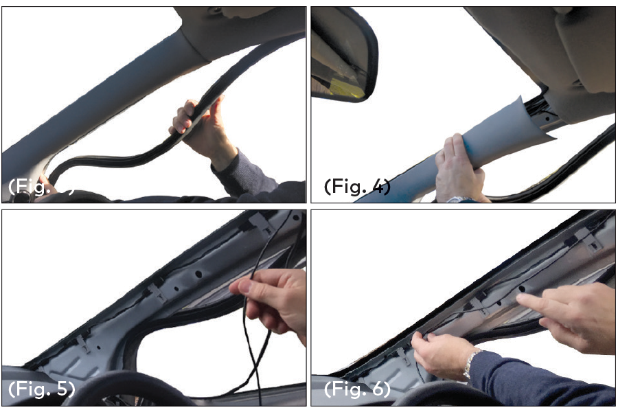
3. At the farthest end of the roof lining the output cable needs to then be routed along the A pillar that is closest to the fuse box of the vehicle. You will need to remove the door seal (Fig 3) and A pillar cover (Fig 4) to route the cable. Route the cable all the way down to the end of the A pillar where it meets the dashboard.
4. Attach the output cable to any existing cable(s) that may be housed in the A pillar (Fig 5 & 6 )
*NOTE: The A pillar used to route the cable is not always the driver’s side one as shown. Refer to the vehicle owner’s manual to determine location of fuse box in your vehicle. The output cable needs to be routed in the A-pillar closest to the fuse box.
HOUSING THE OUTPUT CABLE
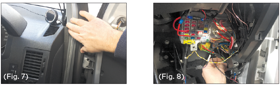
1. Where the output cable from the A pillar meets the side of the dashboard, the output cable will then need to be routed towards the direction of the fuse box by concealing the cable along the side of the vehicle dash (Fig 7).
2. Any excess output cable length can be wrapped and held together with a cable tie when it reaches the fuse box.
3. Tuck away any excess output cable behind the fuse box (Fig 8)
4. If required, peel off the control box label to attach the control box to the vehicle (near the fuse box) with the adhesive tape.
CONNECTING TO THE FUSE BOX
*NOTE: Refer to your vehicle’s fuse layout panel to determine the permanent power fuse for constant and ACC power feeds. The hard wire cable has two connections, the yellow being constant power which powers the camera while your vehicle is parked, and the red connection which will power the camera while the vehicle is started. It is important that this is installed correctly. Incorrect installation may result in sub optimum operation or damage.
1. Open your vehicles fuse box and remove a fuse from one of the constant powered slots (Horn will normally be constantly powered) being sure to note where you have removed the fuse from.
2. Insert the constant power cable (yellow) into the empty slot in your vehicles fuse box that you have removed the fuse from.
3. Remove one of the fuses from one of the ACC powered slots (Your vehicle should have a fuse labelled ACC which will only be powered when your vehicle is powered up) being sure to note where you have removed the fuse from.
4. Insert the ACC power cable (red) and insert it into the empty that the ACC fuse was removed from.
5. Ground the black cable from the hardwire kit onto your vehicles chassis.
6. Tuck away any excess red input cable behind the fuse box.
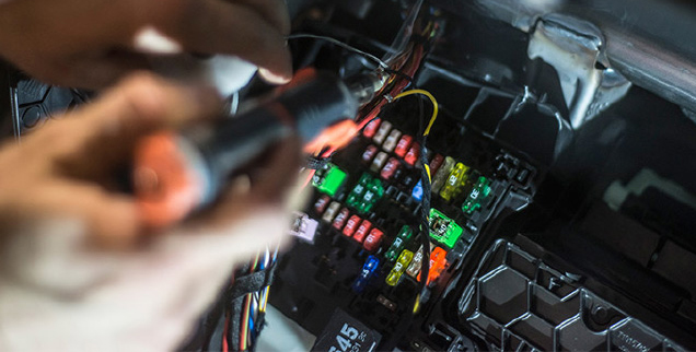
*NOTE: To determine constant and ACC power feeds fuse use a voltage meter.